

How to Export Gerber Files from Eagle
As Gerber is the industry standard file type, It’s therefore easily recognized and processed by our manufacturing equipment.Export Gerber files form eagle may not be familiar to some of our clients.so we will proceed with a step-by-step description in the following section.
Generating Gerber Files
This guide assumes that you have finished designing your PCB within Eagle, and that you have a stored file in the .brd format. We must extract Gerber files from the .brd file using Eagle’s Cam Processor software. Steps for this extraction are outlined below:
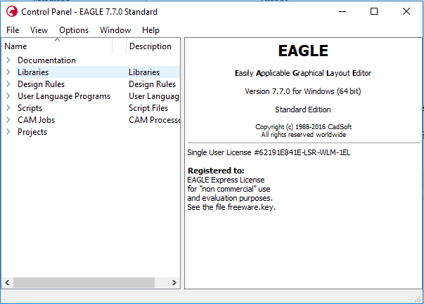
1.Open the control panel for Eagle
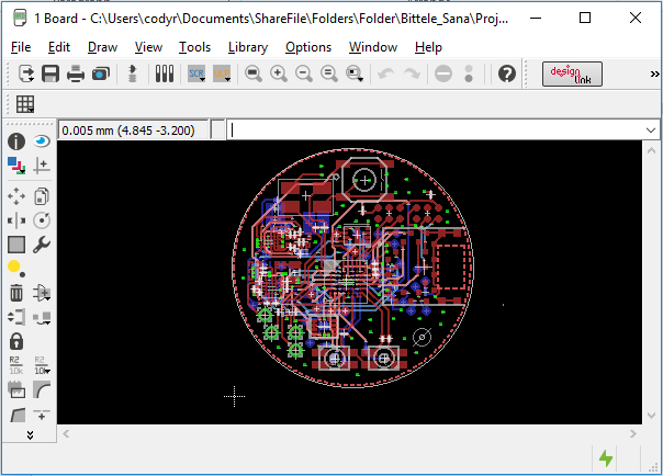
2. Select File -> Open -> Board, and navigate to the .brd file that you would like to work with

3. A window showing the PCB layout should now appear, as shown below:
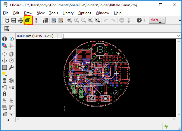
4. Select the camera icon from the top ribbon (highlighted below), or select File
-> Cam Processor
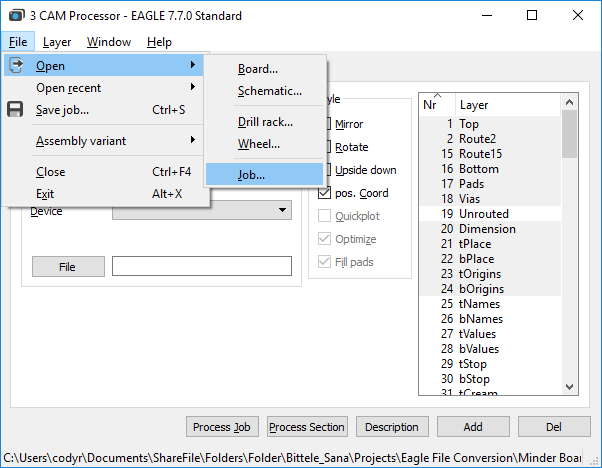
5.A new window will appear for the Cam Processor. In this window, select Open -> Job, as shown:
6.Select gerb274x-mill-drill.cam. This job file is set up for a 2-layer board, but the following examples show how to specify additional layers with the job if you are required. In the Output section of the Cam Processor window, select the File button, and navigate to the location in which you would like to store the converted Gerber files. Choose a file name for the layer, for example: the Component Side tab could have the file name “TopCopper.cmp”
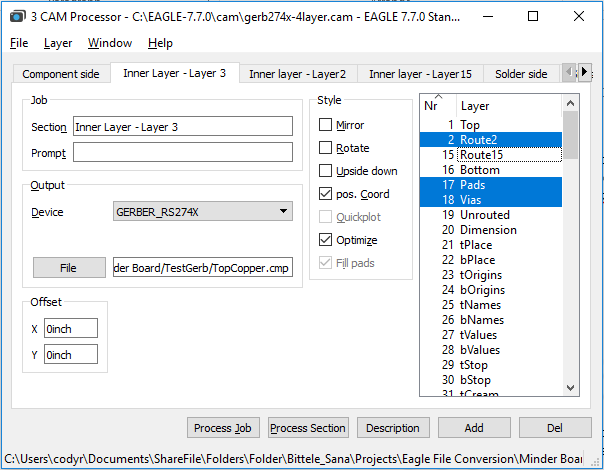
7.If the board is greater than 2 layers, we must use the Add button in the bottom-right corner of the window to duplicate one of the existing copper layers, and modify its settings.

8.Re-name this layer in the Section field of the Job section, then choose the copper layer that it represents from the scrolling list at the far right of the window. For a regular inner copper layer, you should only need to select the copper layer itself (Route2 in above picture), the Pads, and the Vias.
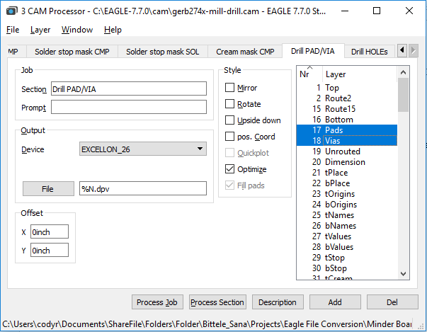
9. Now for the drill files; first choose the tab called “Drill PAD/VIA”, and ensure that the “Pads” layer and the “Vias”layer are selected (these are not selected by default). Also scroll down to ensure that the “Drills” layer is selected, although this one should be selected by default.
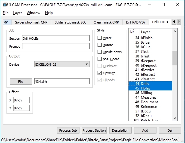
10.Next, choose the tab called “Drill HOLEs”, and scroll down in the layers list to ensure that both the “Drills” layer and the “Holes” layer are selected. (Holes is selected by default, but not Drills)
11.Next, choose the tab called “Drill HOLEs”, and scroll down in the layers list to ensure that both the “Drills” layer and the “Holes” layer are selected. (Holes is selected by default, but not Drills)
12. Once you have specified File destinations for each of the tabs within the Cam Processor window, select the Process Job button at the bottom of the window.
13. Check the file path that you specified in step 7 to ensure that your Gerber files have been generated successfully. If you have access to a Gerber Viewer software, you can use it now to verify that the contents of your design files were preserved through the conversion procedure.
Drill File Secondary Option
If you already have the Gerber files, and simply need to export your PCBs drill files on their own, then worry not! The process for this is actually quite straightforward; it incorporates only four (4) steps:
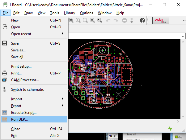
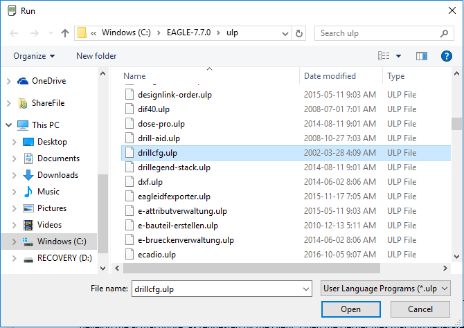
1.From the Board view of your .brd file, select File -> Run ULP
2.Choose the file called drillcfg.ulp
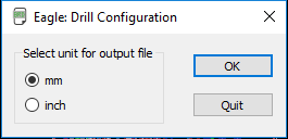
3.Select the measurement units for your drill file. These should match with the measurement units you specified during the design phase for this board. Select Ok.
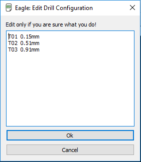
4.Select Ok on this screen. Do not edit the text in this window unless you are absolutely certain of what you are doing
5. Choose a file location for your drill files, and that’s it, you have successfully exported your Gerber files!
PCB Blog
Contact Us
E-mail: [email protected]
E-mail: [email protected]
Skype: [email protected]
Whatsapp: +86 15012972502
Add: 2F, BUILDING H, WANDA INDUSTRIAL ZONE, ZHOUSHI ROAD, LANGXIN COMMUNITY,SHIYAN STREET, BAO 'AN DISTRICT, SHENZHEN, GUANGDONG, CHINA


 Skype Chat
 WhatsApp
  Mail inquiry