

Can I find a short on the PCB with a multimeter?
Can I find a short on the PCB with a multimeter?
We can’t just give you a one-size-fits-all answer.The reason that there is general info on how to approach debugging a pcb, and not on the exact steps is because every PCB is different and every symptom is different, and you, the person debugging is the only one that has the information necessary.Usually the steps to debug a pcb are:
Study the schematics. Learn how the pcb is supposed to work.Define exactly what happens that you think is the problem.Find the portion of the PCB that is responsible for that behavior.Calculate what the different voltages should be.
Then measure the same voltages with the multimeter.The bug will be close to the one measurement that is off. Sometimes it is a failed or desoldered component. Capacitors are the most common suspects. Damaged pcb leads are the second most common.
It is highly unlikely that your device has developed a short between traces on the PCB.You need to give us a lot more information. What is this? What makes you think it is a “short”? You don’t know how many times I’ve had someone bring in their electronics and tell me “it has a short in it”.Such as the power supply light blinking. Are you sure it isn’t the power supply that has had a component blow out?
Simply poking the leads of a multimeter randomly into a PCB isn’t going to tell you anything. Some types of components will look like a short to an ohm meter when they are fine, some will appear as some other reading even when bad. Who knows what the pins of an unpowered IC will show on an ohm meter?
Can you disconnect the power supply from the device and check its output? Do you have a way to put a load on the power supply to test it?
Do you have another equivalent power supply to substitute in, to determine if it is the power supply or the device that is bad?
What do you plan on doing once you’ve figured out which part of the device is defective? Every electronic device is different.
let’s assume that you have judged there is a short by the fact that a fuse is blown. I will refer to this idealized diagram of pcb conductor traces for discussing the strategy:

Clip the ground lead of your meter to ground on the pcb. If there is a wide pcb trace around the edges of the pcb, and that trace is connected to metal shields over some components, that is your ground. With the black lead of your meter connected to ground (on one of those shields, for example), and your meter set to a low ohms scale (x1 or x10), touch your red probe to various points on the pcb. When the ohms reading is at or close to 0, then you are touching another grounded point.
Remove the fuse from the clip, or at least do not put a new fuse in the clip. Touch the red probe to each end of the fuse clip. The end that shows 0 ohms is the output side of the fuse, and that is where your short is. (The other end of the fuse is where the power supply comes into the board.) The 0 ohms end of the fuse clip, that is point (1) in the diagram.
The shorted component(s) are connected to point (1), but look at all those pc traces…dozens of components are connected. You could unsolder each of those components one at a time, but that would be like counting on your fingers. Instead, we are going to try to cut the number of possibilities in half, with each test.

Clip the meter’s red lead to point (1). With your #11 Xacto blade, cut the pcb trace between (1) and (2). Does the meter still show 0 ohms?
If YES, then the short is connected to one of these points: 3,6,7,12,13,14,15. If NO, then the short is connected to one of these points: 2,4,5,8,9,10,11. We will assume NO, so your short is among 2,4,5,8,9,10,11.
First, mend the pcb trace you cut, detailed in MENDING A CUT PCB TRACE, below. Now your meter will again read 0 ohms.
Next, cut the pcb trace between (2) and (4). Does the meter still read 0 ohms? If YES, then the short is connected to one of these points: 4,8,9. If NO, then the short is connected to one of these points: 5,10,11. We will assume NO, so your short is among 4,8,9.
Repair the pcb trace between (2) and (4), and keep moving down the tree with this same strategy until you have found the one component that is shorted. When you have removed that component from the circuit, and that capacitor or transistor or diode shows 0 ohms on your meter…and when point (1), with all traces mended, does NOT show 0 ohms, that component in your hand is the one that needs to be replaced.
With all logical processes, there is an infinitude of exceptions that may manifest. I have kept this description as simple as possible, for clarity, and I hope you do not encounter an exception during your first 4 troubleshooting experiences, so your confidence in my strategy will grow.
MENDING A CUT PCB TRACE
Find one component lead on each end of the severed trace. Solder a piece of bare 28 or 30 gauge wire to each component lead, being sure that fine wire follows the path of the pcb trace (does not take a shortcut). Still better, scrape the paint off the pcb trace before you attach the fine wire, and solder the wire down to the trace as well. If you do not have some small gauge wire like Kynar wire-wrapping wire, you can use a single strand from a piece of stranded hookup wire.
AN ALTERNATE CASE WHERE THE TRACE-CUTTING TECHNIQUE WOULD NOT BE PRACTICAL.
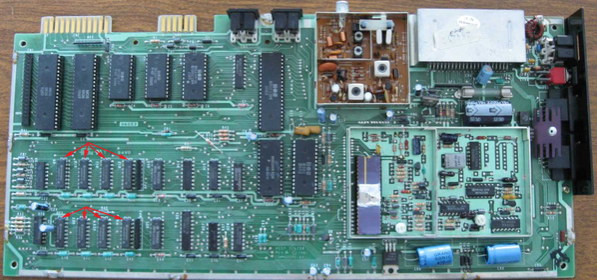
This is the circuit board from a Commodore 64 computer. The red arrows point at 8 dynamic ram memory chips, each chip being 64K * 1 bit, 8 bits altogether. The 8 data pins from each of these chips, arranged in 0–7 order, form the data bus, which is connected to every integrated circuit on the two-sided board.
In a hypothetical case, the computer will not boot up, just shows a black screen. We find that +5vdc power supply is good, but peak to peak amplitude of all lines on the data bus is less than 1 volt.
From a lot of experience, I have learned that there is likely a short in one of the memory chips. They are difficult to unsolder and remove, but experience shows that the bad chip is usually hotter than the others! Touch each chip in turn, and if one of them is uber-hot, replace that one. If the temperature difference is not enough that you can be sure using the finger-tip test, then hook a silicon diode across your meter probes, with the meter in diode mode. The meter should read approx 0.600, which is the switching voltage of the diode. That voltage will change according to the temperature of the diode, so you can use it as a temperature probe to find the hot chip.
The least destructive way to remove the defective chip is to use the Xacto knife to cut each leg of the IC, one at a time. Remove the black IC body, and one at a time grip an IC leg with long-nosed pliers, heat the joint, remove the leg, and carefully ream the hole with a sharp-pointed soldering aid. It might be good practice to solder in not the replacement IC, but instead a low-profile socket. C-64 was a cost-conscious design, but I did see some of them whose RAM chips were socketed at the factory.
Go to the PCB knowledge Page
Go to the PCB design resources page
Back to the technology data
PCB Blog
Contact Us
E-mail: [email protected]
E-mail: [email protected]
Skype: [email protected]
Whatsapp: +86 15012972502
Add: 2F, BUILDING H, WANDA INDUSTRIAL ZONE, ZHOUSHI ROAD, LANGXIN COMMUNITY,SHIYAN STREET, BAO 'AN DISTRICT, SHENZHEN, GUANGDONG, CHINA


 Skype Chat
 WhatsApp
  Mail inquiry