

Solder Shorts on a PCBA board
Solder Shorts on a PCBA board
Solder shorts are generally on the increase in the wave soldering process.
This is due to the ever decreasing component pitches used in manufacture. In the past, the pitch of terminations were 0.050". Now we see many conventional terminations being used on a 0.025" pitch.
Solder shorting occurs when the solder does not separate from two or more leads before the solder solidifies. Increasing the flux solids or quantity is one way of decreasing
shorting. A reduction of the lead length and the pad size will reduce the amount of solder being held on the base of the board.
1.A solder short on a connector with a 0.025" pitch.
It shows a connector on a 0.025" pitch that was improved through changes in the pad design. Alternative pads were increased in length on the exit side of the wave. This made the actual separation distance between the adjacent termination larger and decreased the shorting.
2.A rare solder short on the top side of a printed board.
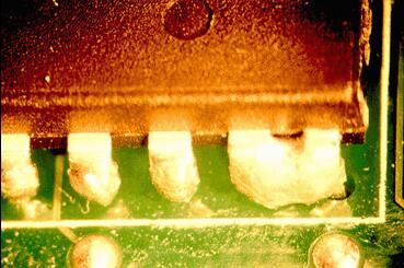
The solder shorts were seen on IC leads on a single sided printed board. During contact with the wave, the pressure was so high that shorts occurred due to excessive solder
penetration. This type of defect is more likely to be seen on any of the vibrating waves produced by three companies to aid surface mount assembly. It would be more likely
to occur on single-sided board as the hole-size-to-lead ratio is often larger, due to the tolerances on these cheaper laminates.
3.Shorts on a pin grid array.
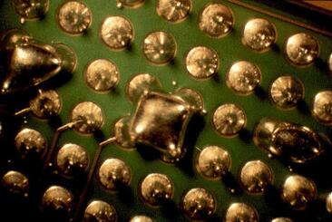
Shorts are seen on a pin grid array (PGA) device. Due to the close proximity and the number of pins, the solder separation is impeded from the base of the board. Shorting
can occur due to poor fluxing, incorrect pre heat or wave separation. All shorting can be decreased through good design rules, with reductions in pad size and component lead
length. In the case of the example shown in Figure 3, it was necessary to change the solids content of the flux while still retaining a no clean process. Using a hot air
knife failed to improve the process due to the high mix of boards and pin lengths.Solder shorts are becoming a major problem in wave soldering, particularly as component
pitches continue to decrease
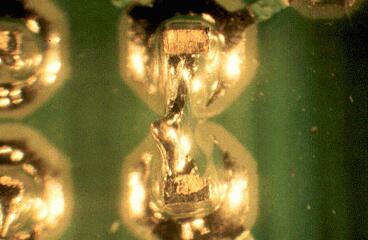
4.Smaller pads would have decreased the likelihood of this short occurring.
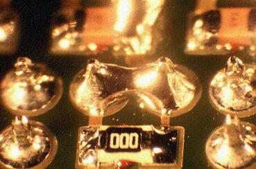
The pin length is correct at 1-1.5mm, but the surface pads could be reduced in size. With smaller pads, less solder is retained on the board to short between pins. If this is the only defect area on the board, then a nice fixit is a glue dot placed between the two pins by your placement department.
As boards become more heavily populated, shorting becomes more of a problem. A hot air knife after the solder wave can eliminate some problems, but most can only be fixed by good design. Increasing the flux solids will improve the drainage on all joints.
5.Solder shorts are common on SOIC devices.
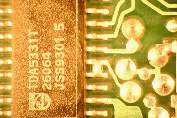
SOIC devices should be the limit for underside mounted components. Decreasing the pitch below 0.050" pitch will always increase defect levels or increase engineering time
coaxing the process to solder 0.025" parts. Solder shorts are common on SOIC devices. If the short is in the middle of the row and the pad width is below 0.022", it is a
process problem. Fluxing is the first area to examine, then look at adjustment to the contact time in the wave. Often changing the angle of the conveyor eliminates this
defect. Unfortunately many wave soldering systems do not now allow this adjustment.
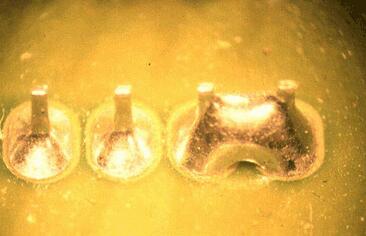
6.Shorting at the top of the pins on a QFP.
The shorting example is seen at the top of the pins on a QFP device and may be improved by increasing the solid of the flux. This defect is often caused by incorrect pre-
heat or limited time in the wave. The thermal effect of the device can tend to cool the solder, slowing drainage. On some occasions when the shorts are at the top of the
lead form, it is a solderability issue. If a lead area close to the plastic body is slow to wet, it is also slow to drain, hence a short. As with SOIC devices, QFPs benefit
from solder thiefs on the trailing edge of the parts, but only if the solder shorts are always on the last two pins. The solder thief pad should always be a minimum of three
times the length of the last pad and on the same pitch. With QFPs, the device is also positioned at 45° to the direction of travel through the wave. Try gluing some
components to the base of a glass plate; this will help you convince both engineers and design engineers that design for manufacture is a must.
Wave soldering devices below 0.050" pitch should be avoided and questioned during design for manufacture (DFM) reviews of new designs. Yes, it can be done, but it takes a
lot more effort from machine and process engineers. Soldering 0.032" pitch can be achieved, 0.025" is problematic and using 0.020" on the base of the board requires more
rework staff.
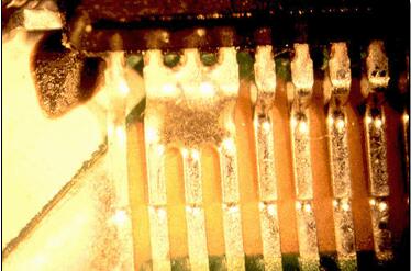
7.Poor solderability of bare tips caused these solder spikes and subsequent short.
Solder shorts can result from poor solderability of the pins.there are solder spikes on the ends of the leads due to the poor solderability of the bare tips of the leads. If a termination is slow to wet it is generally slow to drain hence increasing the incidence of solder shorting.
PCB Blog
Contact Us
E-mail: [email protected]
E-mail: [email protected]
Skype: [email protected]
Whatsapp: +86 15012972502
Add: 2F, BUILDING H, WANDA INDUSTRIAL ZONE, ZHOUSHI ROAD, LANGXIN COMMUNITY,SHIYAN STREET, BAO 'AN DISTRICT, SHENZHEN, GUANGDONG, CHINA


 Skype Chat
 WhatsApp
  Mail inquiry